First Power Supply Investigation
Started looking over the power supply tonight, since that’s the logical first part to power up.
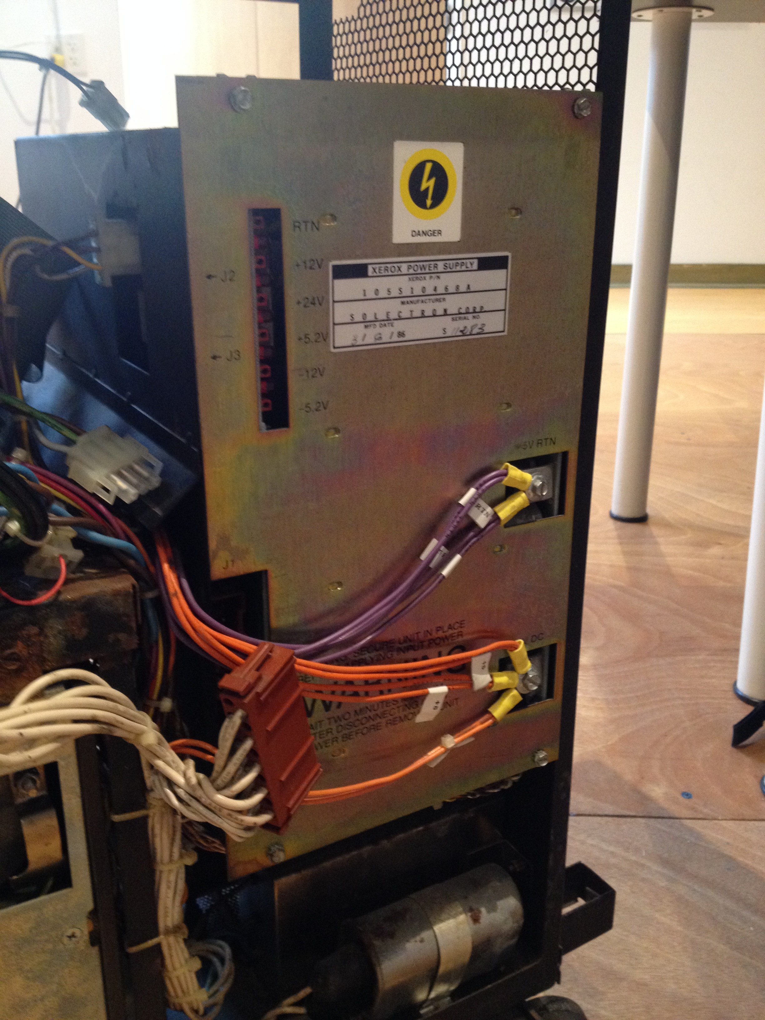
The PSU installed in the system. The red connector is all the transformer taps, and the screw terminals are the high-current +5V.
Ever since I’d first opened the system’s case I’d wondered why there was both a power supply box as well as a giant transformer in the unit. It turns out that the transformer is part of the power supply, it was just too big to fit in the box! There’s a wiring harness to take 120V into the transformer and send all the various secondary windings/taps into the power supply.
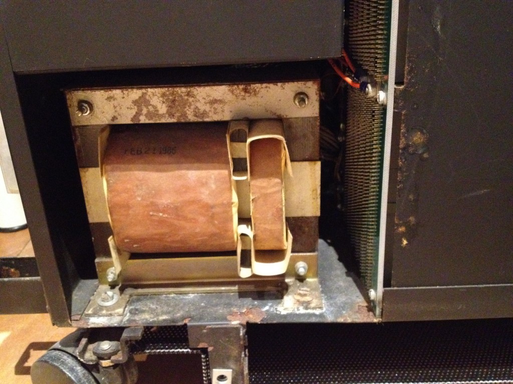
The transformer used to power the linear board of the PSU via many windings/taps.
I had expected the PSU to be a switchmode power supply, but it looks like that’s only half true. There are a total of 5 rails (or possibly 6, it lists +5.2V and +5V which may be the same rail). It looks like 4 of the 5 (the lower current rails, all except +5) are done via linear regulation, and +5 has its own entire board that implements a primitive-ish switchmode power supply. A lot of the components have Xerox-specific part numbers, so figuring out how things work is a bit difficult in places.
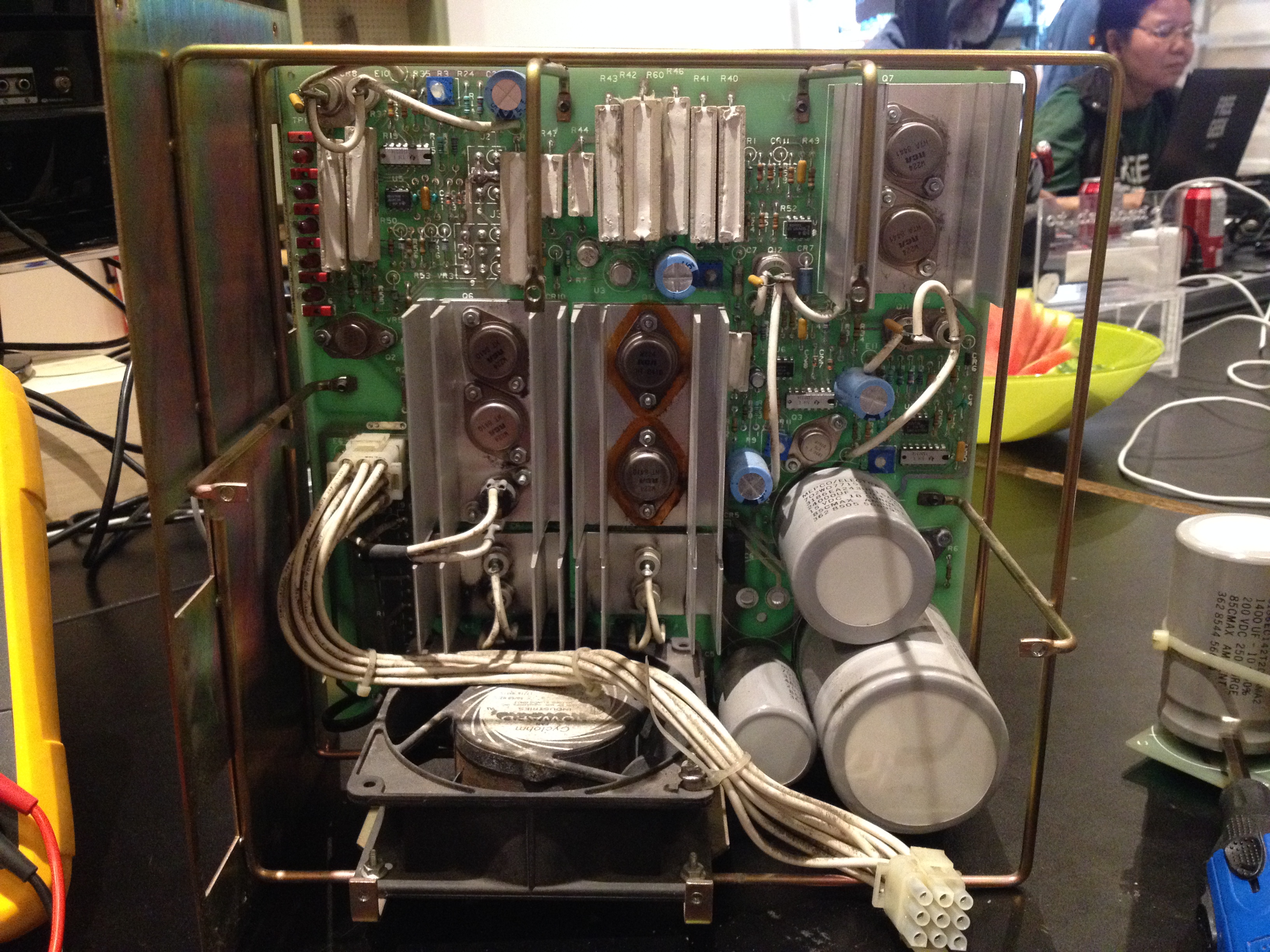
One of the two PSU boards, seems to be linear supplies for all the lower-current rails.
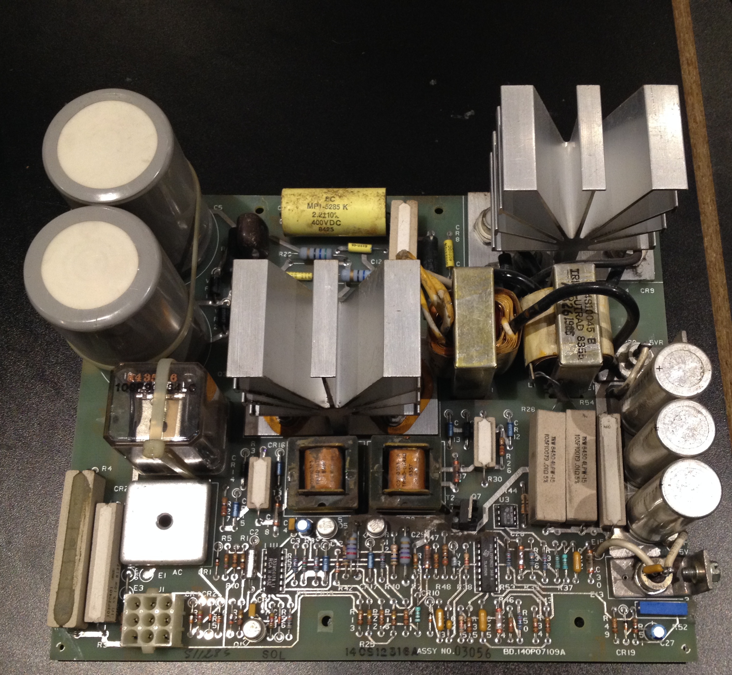
One of two PSU boards, seems to be the +5V SMPS.
Tonight I started pulling the biggest caps off the board (which is easy, since they connect with bolts!) and putting DC across them to check leakage and see if any need reforming. Got two done tonight, and both look OK after a couple hours of voltage across them, 4 more to go.
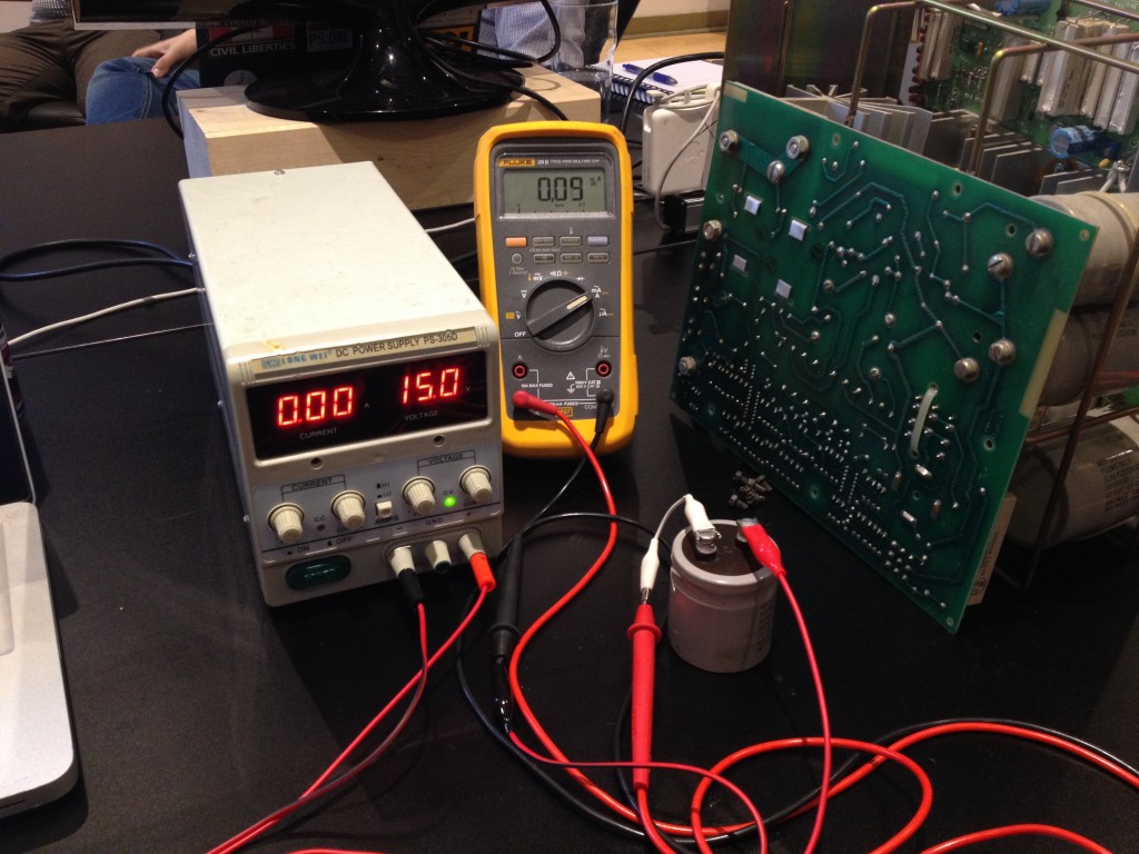
Testing capacitors to see if any need reforming.
Lots of cool and unusual things on these boards, at least for someone now used to 2015 electronics! A bunch of us at the lab spent a lot of time looking over the boards in detail marveling at all the high-power parts that bolt into the board and unusual parts like 4-terminal wirewound resistors and now-uncommon IC/transistor packages.
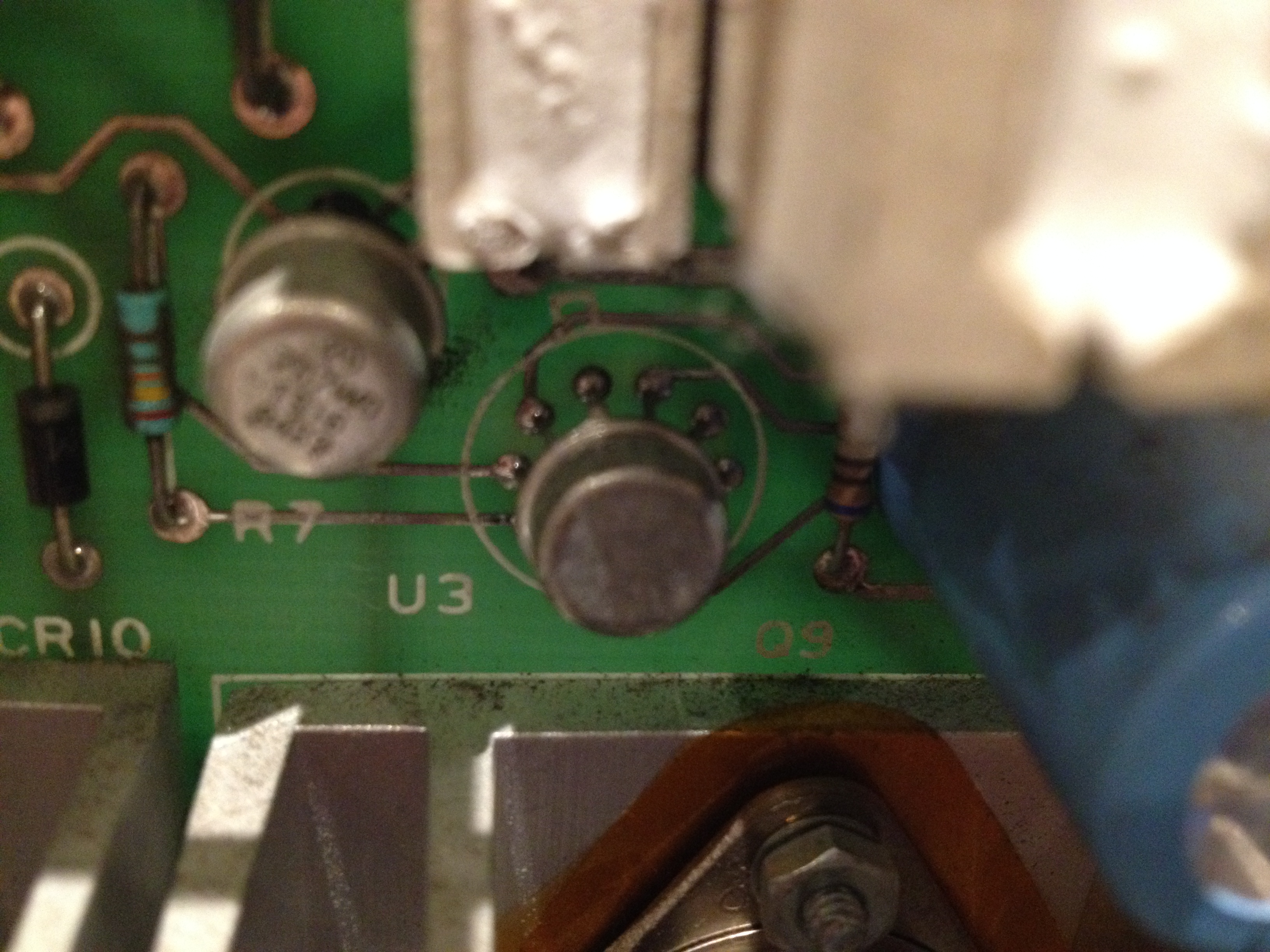
An interesting package on the PSU’s linear board. Old op-amp maybe?
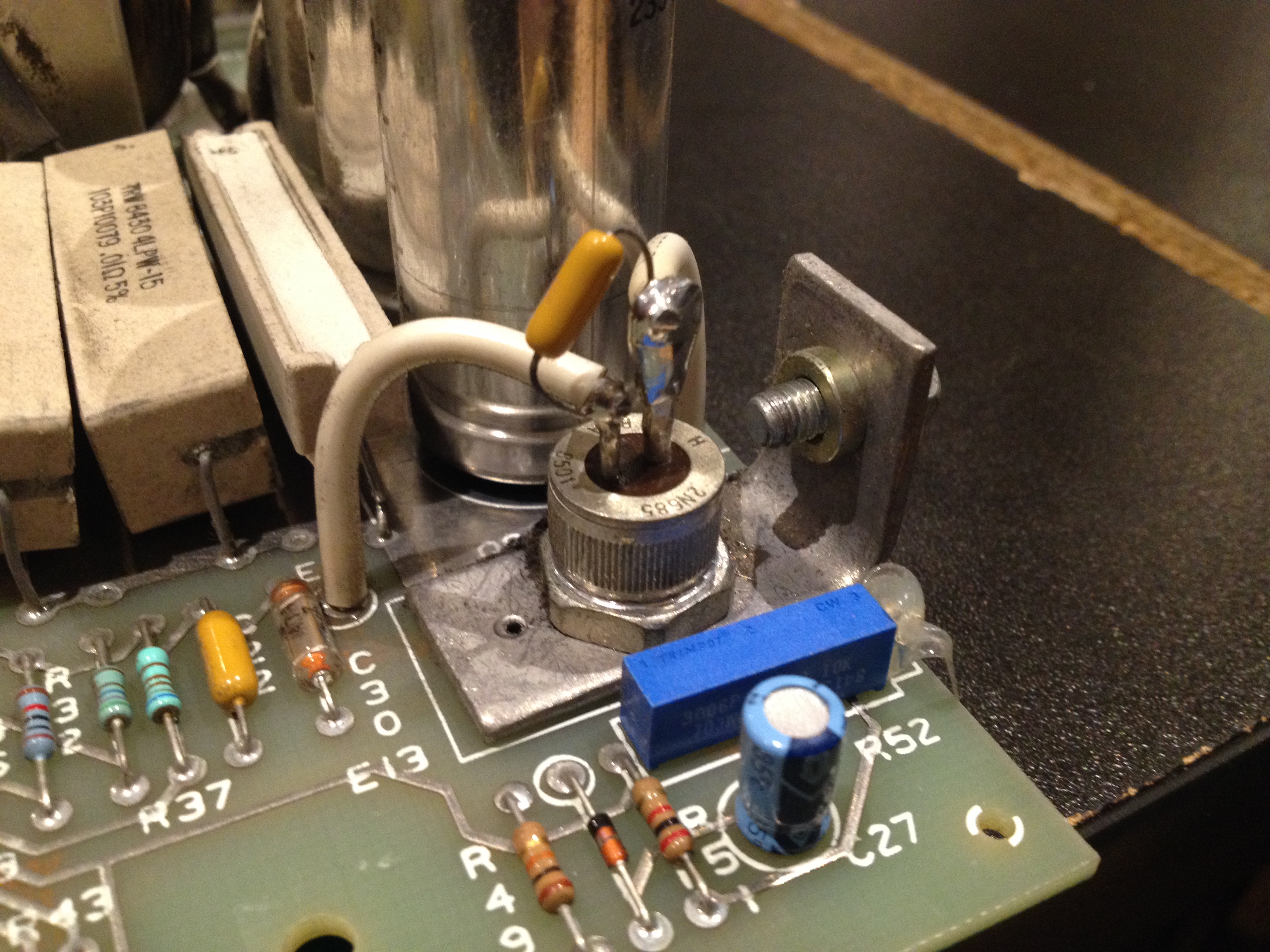
An SCR bolted to the +5V output. Not sure what’s going on with this, maybe for power sequencing?
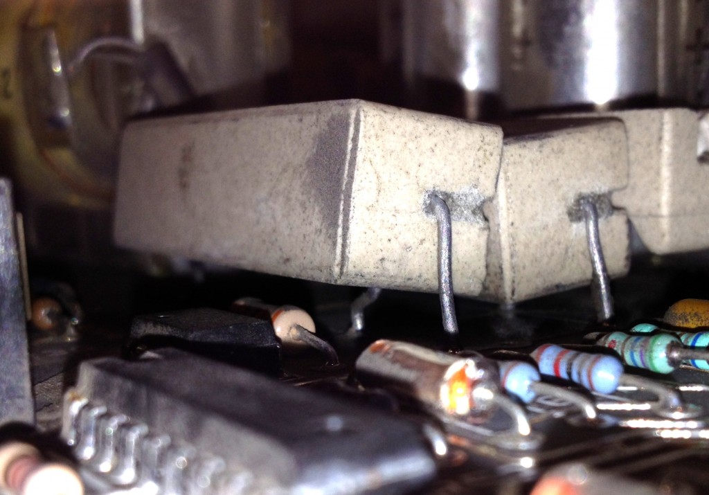
A 4-terminal wirewound resistor used on the output of the +5V supply for current feedback.
The list of caps that need testing to confirm <= 50uA leakage and/or reforming is:
- Linear board C1 – Not yet tested
- Linear board C2 – OK
- Linear board C5 – Not yet tested
- Linear board C6 – OK
- 5V board C5 – Not yet tested
- 5V board C6 – Not yet tested
Leave a Reply