Maintenance Panel
Photos
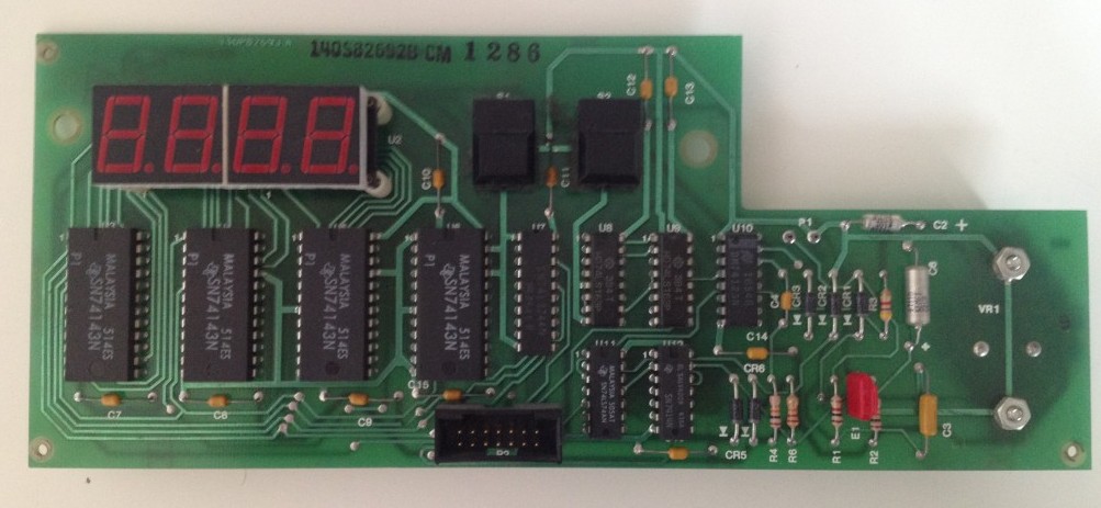
The maintenance panel PCB
Connectors
P1
- Type: Unknown 2 pin connector
- Use: +12VAC for MPVcc/RTC clock
- From: Power Distribution Board connector P2
P2
- Type: 2×7 0.1″ male header
- Use: Signals and power between MP and IOP
- From: IOP connector J11
- Pinout:
- → /IncMPanel
- → /ClrMPanel
- → BlankMPanel
- ← /PowerFailed
- → /SetTime
- ↔ GND
- ↔ GND
- → IOPVcc (+5V from IOP)
- → IOPVcc (+5V from IOP)
- ← /ENMPSignals
- ← /1HzClk
- ← /AltBoot
- ← /BootReset
- ← MPVcc (to IOP)
Leave a Reply