Current Limiting/Measuring Box
I’m still working on reversing the PSU linear board into a schematic (making good progress and learning a lot), but the next physical step will be to start bringing up the linear part of the power supply. To do this, I want to be able to limit the amount of current it can draw at first, to avoid potential smoke-releasing should anything still be wrong with it. The traditional way to limit current to line-voltage devices has been to put a light bulb in series with the device you’re testing, which both limits current and lights up as more current is drawn, which lets you know it’s using more current.
I had a box sitting around the HackLab which I’d built it to control various parts of our laser cutter many years ago (but which I’d since replaced with a fancier PLC-based solution), so modifying that into a current limiting box seemed to make sense. I rewired the switches so I have one regular bank of switched outlets and one bank of 2 or 3 outlets in series. This lets me plug in the device I’m testing into one, a light bulb into another, and (optionally, with a switch to select either way) an ammeter into the third. Should make testing the power supply a bit easier!
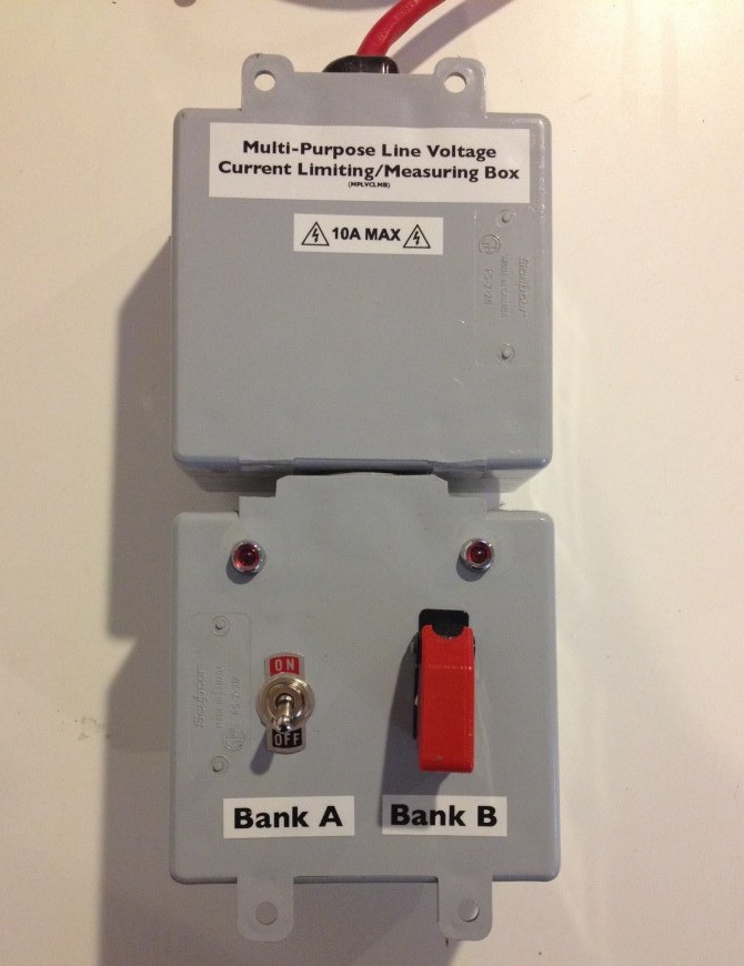
The front of the current limiting box.
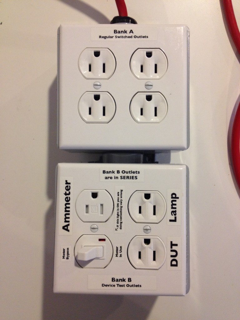
The back of the current limiting box.
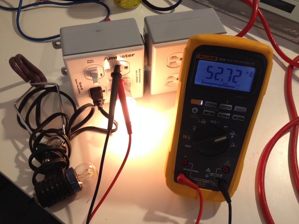
Limiting current through the light bulb in the lower left using another light bulb, and measuring how much current is being used. Still have to make a proper cable to go to the meter, but this works for now.
Leave a Reply