First Light
I’d reversed enough of the PSU’s linear board to generally understand what was going on with it, so figured it was time to start trying to power things up bit by bit.
Starting out with everything except the transformer disconnected and the system connected through a current limiting bulb and variac, I brought the voltage up slowly and… nothing. No current draw at all, no activity. Pretty quickly realized that I didn’t have the power distribution board connected yet, so the power wasn’t getting from the input to the transformer. Connected that and brought the voltage back up, but still nothing. Figured at this point I needed to trace the wiring harnesses out more to figure out exactly where the power was going.
I started tracing and found that the primary of the transformer actually looped through the linear board of the PSU, through the thermal cutout I didn’t understand the purpose of earlier. It turns out the power actually goes through the cutout on the linear board, then to the switcher board, which starts itself up first then closes a relay to give power to the linear side. Without the entire PSU in place, nothing was going to get power at all. I figured out which terminals the whole chain of boards would eventually loop together, and joined them with a wire for the time being. Turning the voltage on the variac back up lead to a loud humming and 60VAC out of one of the transformer taps, finally!

Had to jumper the connector to get the transformer powered without the rest of the PSU. Just like with an ATX power supply, except 120V!
I measured all of the transformer taps and documented them all for future reference, then connected the linear board up. I knew from reverse-engineering the board that it didn’t rely on the +5.2V from the switcher board at all, so the switcher having control over the linear board’s power must be to sequence power for the rest of the system. Since there was no actual load connected, not having sequencing wasn’t an issue and running the linear board on its own was safe.
With a meter on the +24VDC rail, I slowly brought up the variac again and watched the voltage on the rail climbing until it hit +24VDC, then it stopped, right where it should! Looking at the rail status LEDs, all but the +5.2VDC rail were up. I briefly started troubleshooting this before someone else at the lab pointed out that the +5.2VDC rail came from the switcher board, which was not yet connected. Oops.
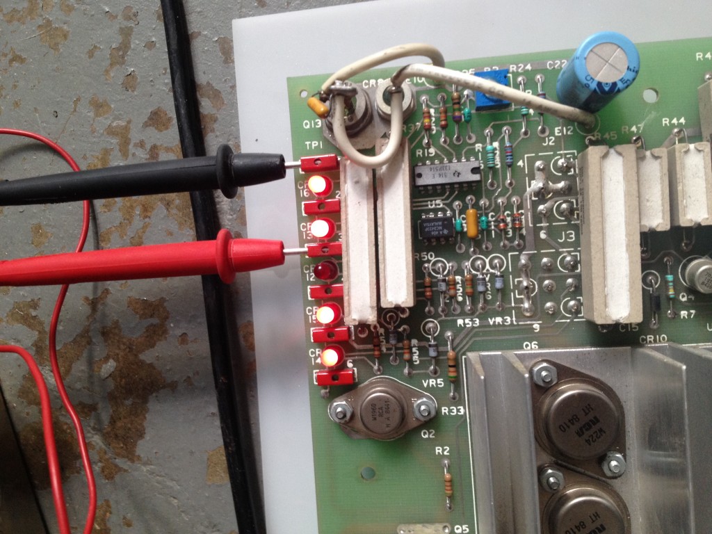
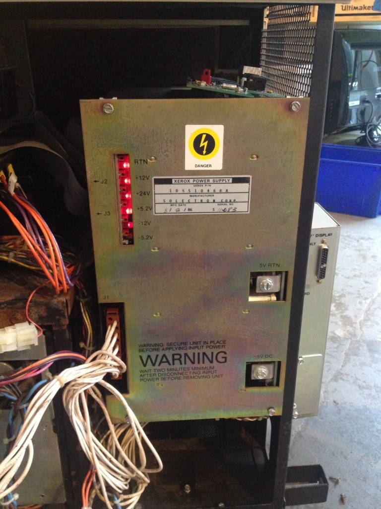
First powerup of this PSU in probably 25 years, all rails except +5.2V (whch wasn’t connected) working!
I ran over the board with a thermal camera, and everything looked relatively okay, so I added a fan next to the board (as it would have in normal operation) and let it run for half an hour or so, with no issues.
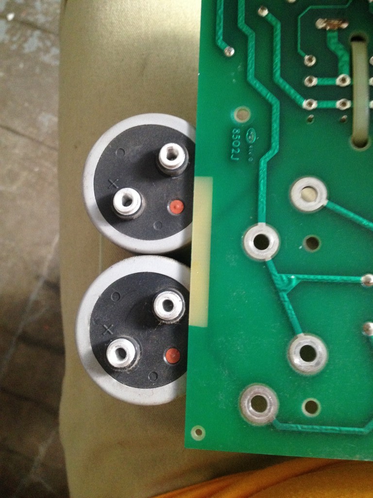
This picture has nothing to do with anything really, but it looked like the capacitors were looking over the edge of the board and were quite surprised.
The switcher board seemed like the next part, I pulled the two largest capacitors off first and made sure they seemed OK, both had <25uA leakage which was fine. I hooked the board up to the linear board, slowly brought up power, and the rail didn’t come up. I vaguely remembered seeing this in the past, where the switching controller wouldn’t start if the line voltage rise time was too slow. Since it took the full 120V without excessive current draw or heating, I switched the line voltage off and back on straight to 120V, and the +5.2V rail came up! I let it run for a bit after confirming the voltage was good, with no problems at all.
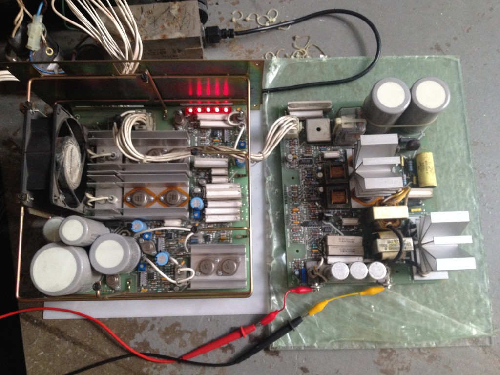
The two boards of the PSU connected up for testing with all rails up and running.
Since the +5.2V rail has the highest power output (at least, from what I can tell by the big bolt terminals for connections and the fact that it has an entire board just for it), I wanted to run it with a test load on it for awhile. I figured it would supply at least 10-20A, and I didn’t have any resistors handy which would handle that for more than a few seconds. I remembered we had a spool of fairly heavy magnet wire left over from another lab member’s project though, and plenty of buckets. As I’d learned from a Mike’s Electric Stuff video awhile back, I measured out enough magnet wire to get about 0.35 ohms (~15 amps) out of the PSU, pushed it all under the surface of a bucket of water, and connected it up. It powered up fine and ran the load for half an hour or so with no issues and nothing getting even remotely hot outside of a couple diodes which was expected.
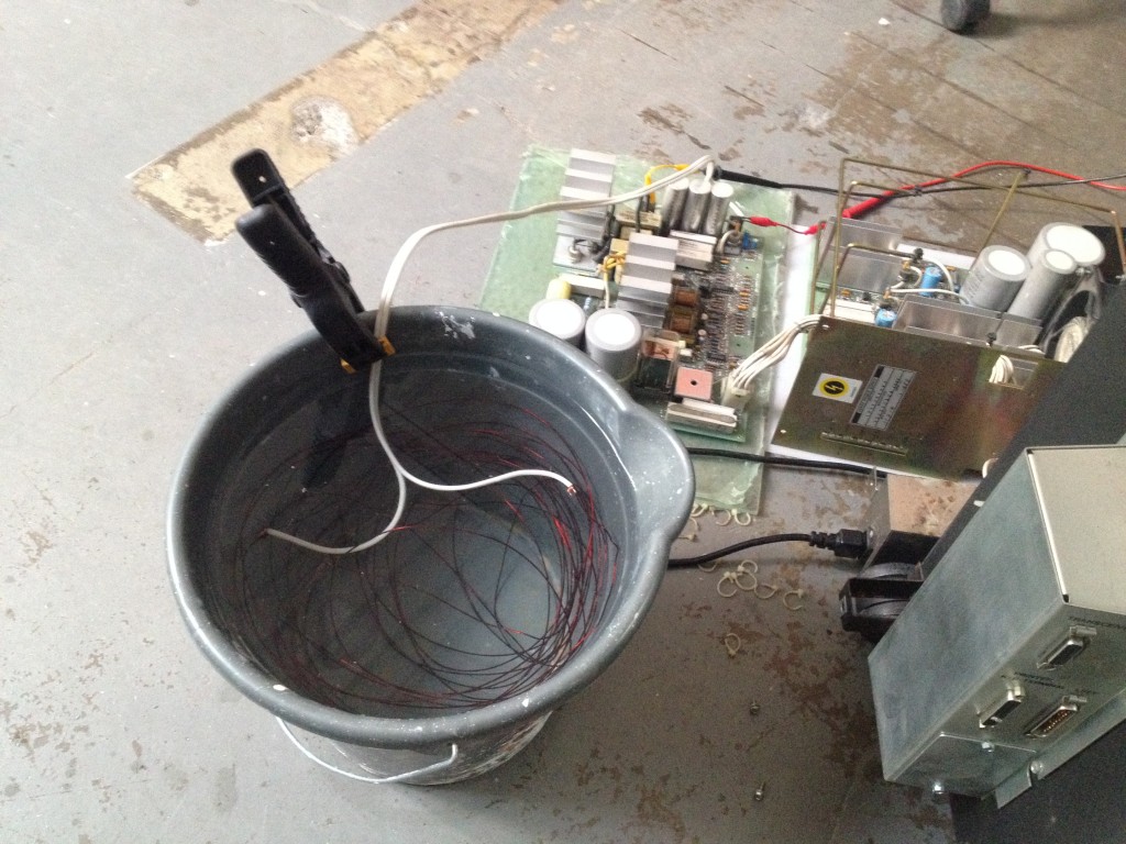
Using a bucket of water and magnet wire as a load for the +5.2V rail.
I tried cutting the length of wire down to increase the load, but it looks like the +5.2V rail shuts down above 15A output. Given how much total this machine draws and how large the +5.2V board is, I have trouble believing it can only supply ~75W, but with no documentation available for it I don’t really know. It’s possible it only supplies ~75W, or potentially some current limiting component has drifted over the years and it’s shutting down early. The fact that the heatsinks only rose a couple degrees after half an hour under the full load it would supply makes me think maybe something is wrong, but we’ll see. The tests I’ve done at least show that the output on all rails is stable under load though and won’t go over-voltage, so I’m comfortable proceeding at this point.

Checking over both power supply boards with a thermal camera.
I do want to finish reversing the linear board and then the switcher board at some point, but at this point I think I’ll move on to other parts of the system and come back to this later. The switcher board has a lot of interesting-looking stuff on it, so reversing it should be pretty enlightening.
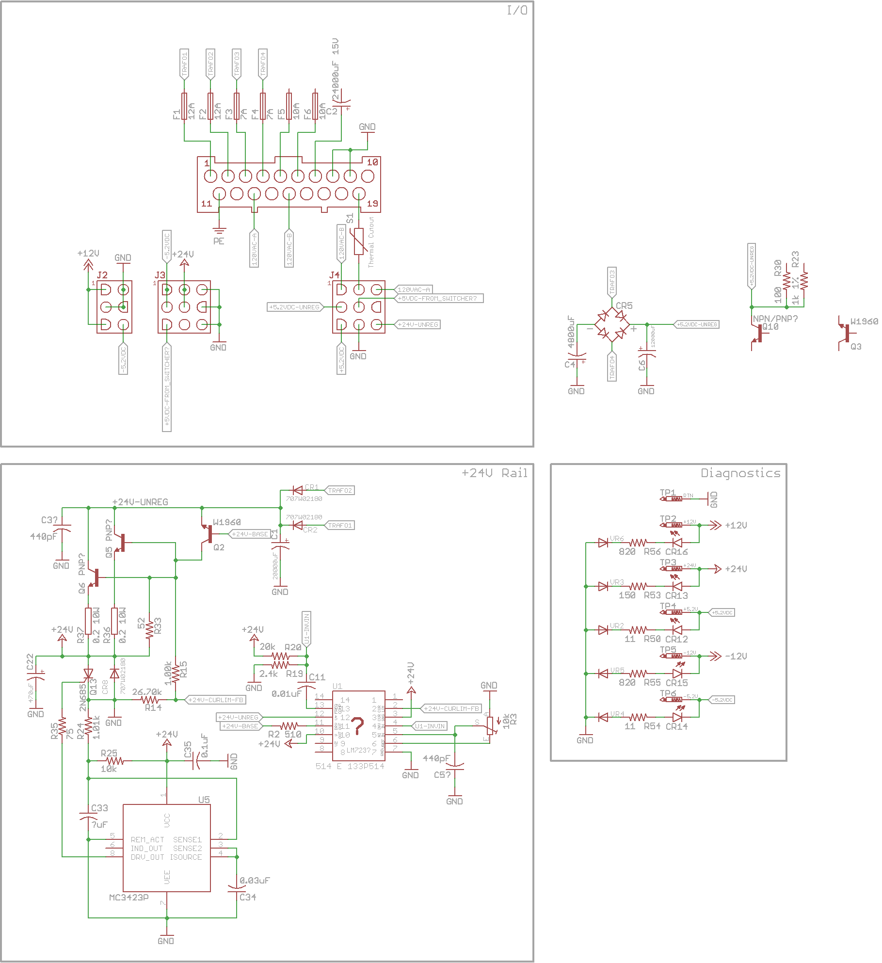
The PSU schematic so far. +24VDC rail is completely reversed out, and starting to work on the +/-12V supply.
Next up is going to be taking lots of pictures of where every connector on every harness is, stripping it all out of the system, and starting to trace all the wires. Mice have eaten a lot of the insulation off all the data cabling and some of the power cabling, so tracing where all the wires go will be the first step in replacing them.
PSU reassembled and installed back in the case.
Leave a Reply