Beeping Out the PSU
Got more or less all the pins on all the connectors traced on the linear board of the power supply this evening! There are convenient test points on the front of the unit for all the voltage rails, which made tracing which pin on which connector much easier than it might have otherwise been. A fast-acting/latching continuity beeper on the multimeter also makes this much easier, as you can just quickly drag the probe across all the pins on a connector until you get a beep.
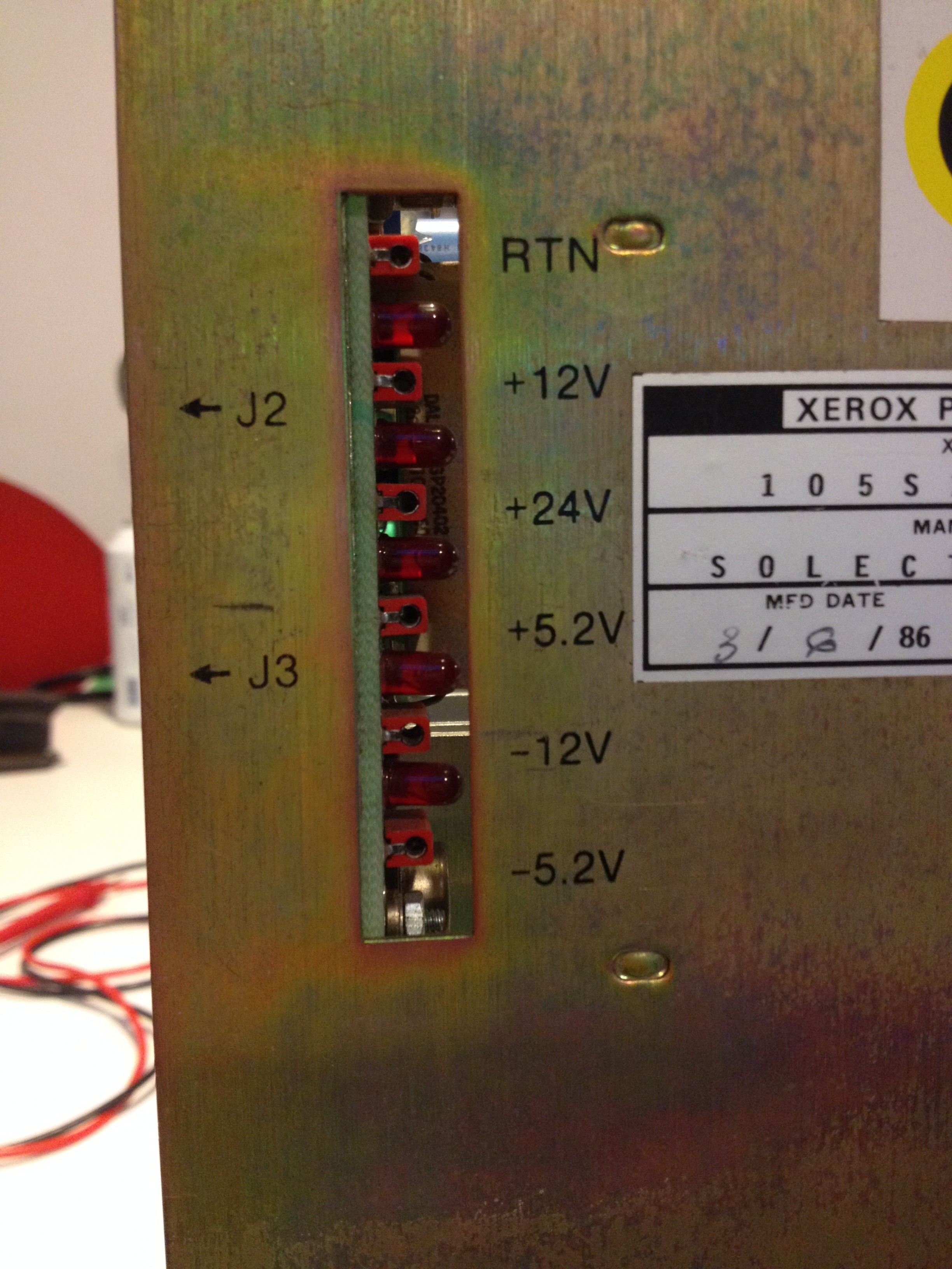
Each rail has an LED and a labelled meter probe test point.
It seems like they didn’t pay much attention to safety on connectors back then, as there are a number of connectors with 120V next to low voltage rails! I’ve documented all the pinouts that I’ve identified so far in the documentation section of this site.
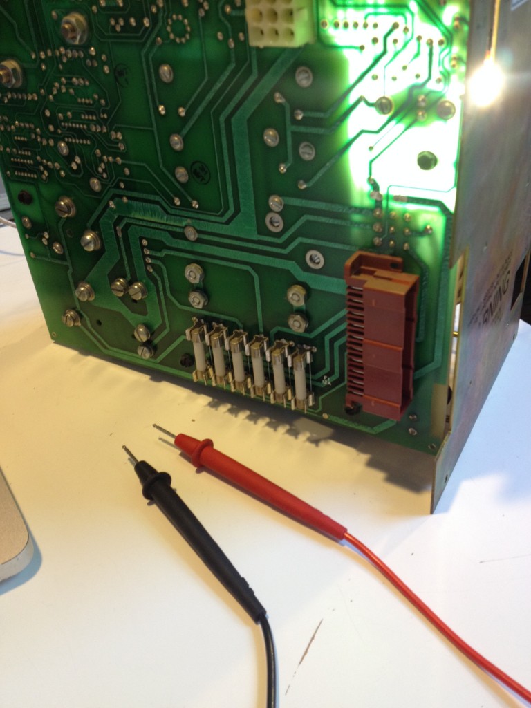
Shining a bright light through the board helps the traces stand out, and makes it easier to see traces on the opposite side of the board.
I’m actually considering putting schematics together for at least sections of the linear board, since it would help me understand how it works as well as assist in any required troubleshooting. It’s complex enough that it would be at least tens of hours to do just the linear board though, so I may just do small sections. This is one of those times where I need to decide whether I just want to understand enough to troubleshoot anything that comes up and get the system working, or whether I want to understand how all the bits work in detail. I tend to lean towards the latter, since reverse engineering boards and understanding the circuits within is something I really like doing.
Leave a Reply