Maintenance Panel
The Dandelion has a small panel on the front under a flip-down cover for performing maintenance and diagnostics on the system. There’s a dedicated PCB behind it that provides some diagnostic output via 7-segment displays, pushbutton inputs to control the boot process, and some RTC clocking circuits. This seemed like a good place to start to check out the system’s electronics, since without the diagnostic output all other tests would be more problematic.

The maintenance panel on the front of the Dandelion
The Maintenance Panel (MP) board normally connects to the I/O Processor (IOP) board as well as the power distribution board, but I wanted to test it individually so connected it to various bench power supplies and an oscilloscope instead. I found a schematic for the MP in the Bitsavers archive, which made this testing go much faster than it would have otherwise.
The MP board normally takes +12VAC from the power distribution board, which is on at all times even when the power switch is off. This power is used to run the RTC, and the 60Hz line frequency is divided down/conditioned and used to clock the RTC. In addition, when the system is turned on the MP then draws power for the LEDs and LED drivers from the system itself.
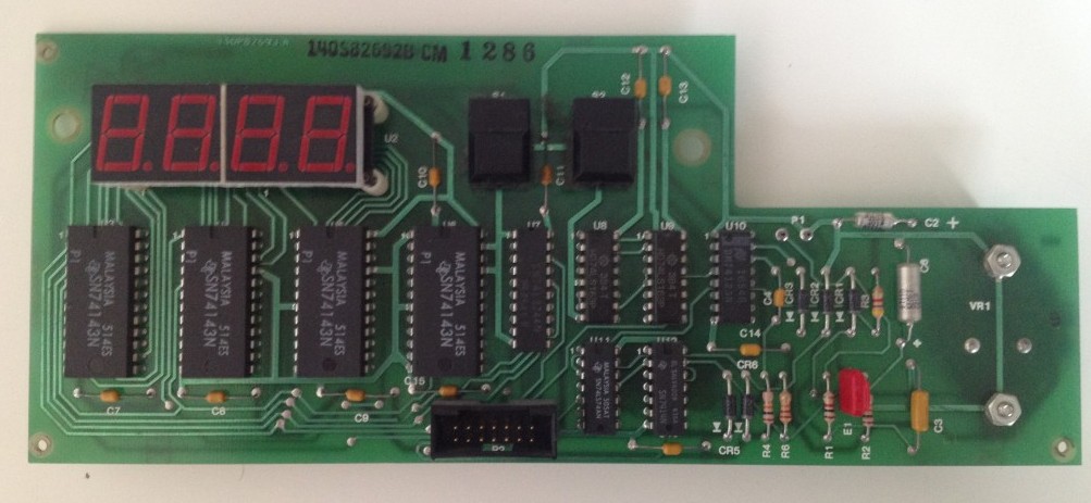
The maintenance panel PCB
I first brought up the board on +12VDC through a current-limited power supply to confirm everything seemed OK, which it was. After checking the board over with a thermal camera and making sure the output was +5VDC, I switched the input to a +12VAC adapter I had around. The 1PPS clock output from the board was working fine, which was a good first sign!
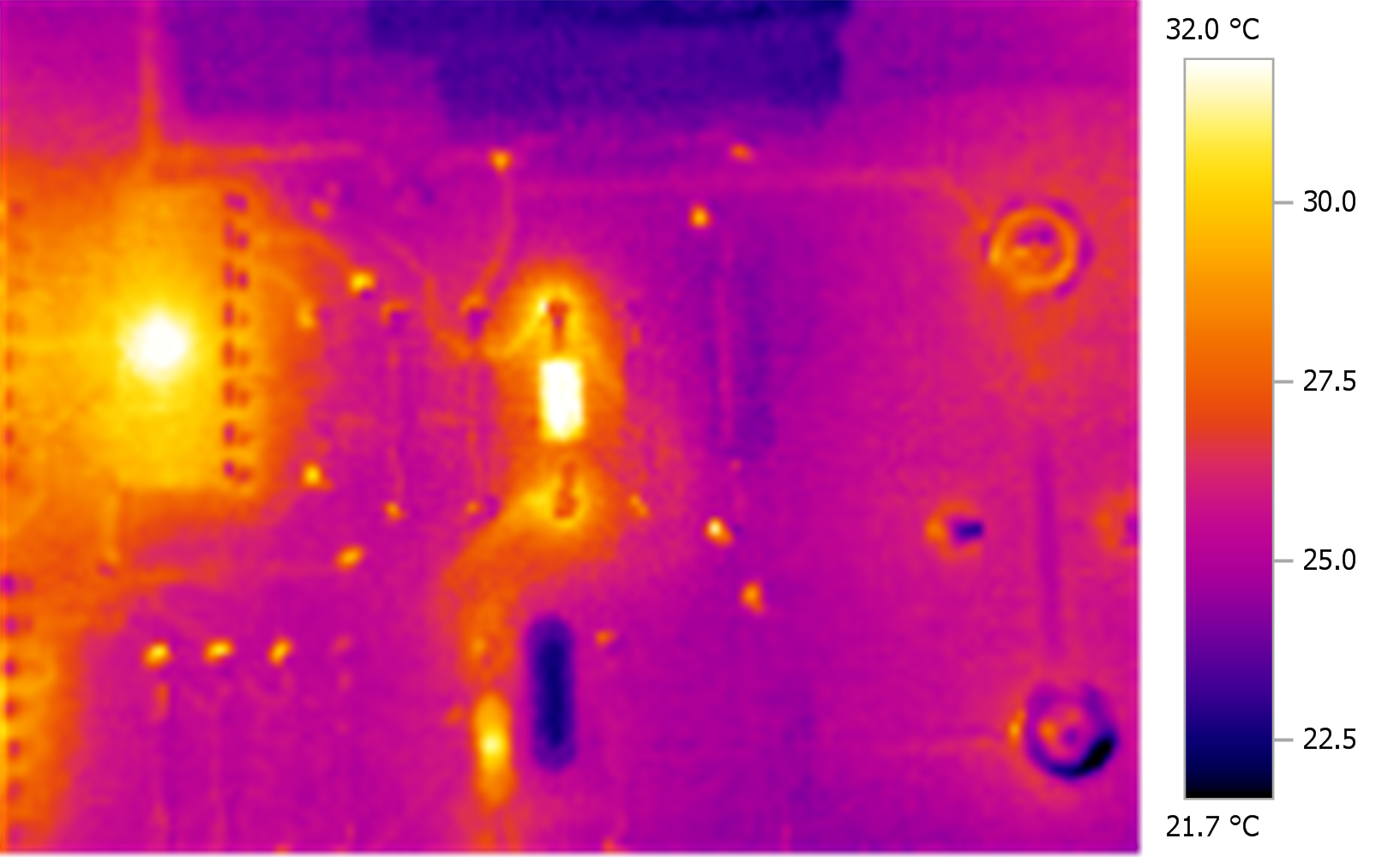
Checking the MP board for any hot spots once it was powered up
The LEDs are powered from the system itself, so I added a +5VDC power supply to run that. Bringing the blanking line low made the LEDs light up, and manually toggling the count line confirmed the display incremented properly. I found a 10Hz line on the board in the RTC clocking circuitry, and connecting it to the count input, the LED display started counting up as intended.
The MP also provides two pushbuttons (Boot Reset and Alternate Boot), which worked fine, as well as power failure detection circuitry. This circuitry sends a notification to the system that the power has failed and therefore the clock is invalid, and the system then asserts a line saying the clock has been set, which clears the power failure notification line. This all worked fine as well, setting and clearing as expected.
So the first bit of electronics in the system works perfectly! Next I’ll probably pull the power supply out of the system and start looking it over.
Leave a Reply